13 Level-2 Bankfull Analysis Workflow
🪛 Practical 🔬 Theory
Level 2 Workflow
This chapter describes the workflow steps necessary to complete a Level 2 (L2) FluvialGeomorph analysis. The purpose of this level is to calculate bankfull channel dimensions.
Create Bankfull Area
The purpose of this step is to use the final bankfull elevation determined in the previous step to derive a final 🗺️ bankfull_area polygon for each reach.
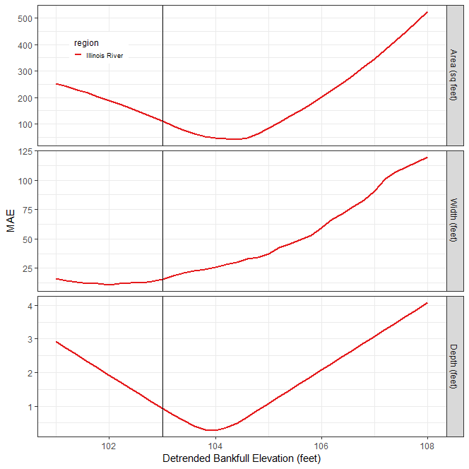
- From the final Estimate Bankfull Report, use the REM bankfull elevation identified in the last step. In the example above, this value was 104 ft.
- Use the
🛠️ Water Surface Extenttool to extract a bankfull area polygon. This tool creates a new polygon feature class named🗺️ banks_raw_xxx, where xxx is the REM elevation specified. - The
🗺️ banks_raw_xxxfeature class must be edited to select only the polygons that represent the bankfull area polygon(s). - Open the attribute table for the
🗺️ banks_raw_xxxfeature class and use advanced sorting to sort first by📊 gridcodeand then by📊 Shape_Area. - Polygons with
📊 gridcode=🧮 1are polygons inundated at the REM elevation. - Typically, the polygons with the largest area represent the channel.
- Begin by selecting
📊 gridcode=🧮 1polygons with the largest area until the entire bankfull area is selected. - Export these selected features to a new feature class named
🗺️ bankfull_area. - Delete the
🗺️ banks_raw_xxxfeature class.
Create Banklines
The purpose of this step is to convert the 🗺️ bankfull_area polygon into polylines and edit into a 🗺️ banklines feature class for each reach. The 🗺️ banklines feature class will have two records, one representing the left descending bankline and another the right descending bankline for the stream reach.
- Use the ESRI
🛠️ Polygon To Linetool to convert the🗺️ bankfull_areapolygon feature class to a new polyline feature class named🗺️ banklines. - Add the following fields to the
🗺️ banklinesfeature class:📊 ReachName:🧮 Text (50)- The purpose of this field is to store the reach name.📊 bank_id:🧮 Long Integer- The purpose of this field is to uniquely identify each bank.📊 bank:🧮 Text (50)- The purpose of this field is to designate which bank is the🧮 right descendingbank and which is the🧮 left descendingbank.
- Start editing the
🗺️ banklinesfeature class. - Use the ESRI
🛠️ Explode Multipart Featuretool to explode any multipart line feature in the🗺️ banklinesfeature class. - Add the
🗺️ flowlinefeature class to the map. - Use the ESRI
🛠️ Split Toolto split the line features at the downstream and upstream ends of the🗺️ flowlinefeature class. - The features in the
🗺️ banklinesfeature class should not extend past the end of the🗺️ flowlinefeature. - Use the ESRI
🛠️ Split Toolto trim any tributaries from the🗺️ banklinesfeature class. - The goal of this step is to have only two features, one representing the left descending bankline and another the right descending bankline. Delete all other line features.
- Ensure that the banklines are digitized in the upstream direction (like a
🗺️ flowlinefeature class). Edit the🗺️ banklinesfeature class to ensure that each bankline is digitized beginning with the downstream end and digitized upstream. - While editing, select a
🗺️ banklinefeature, choose to edit vertices. Ensure that the red endpoint is at the upstream end of each bankline. - Use the
🛠️ Reverse Directioncommand (aka flip) to ensure each bankline is digitized in the upstream direction. - Check that each bankline is digitized in the upstream direction (red endpoint at the upstream end) before going on to the next step.
- In the
📊 ReachNamefield enter the reach name. - In the
📊 bankfield, enter the string🧮 right descendingor🧮 left descendingto designate which bank each line represents. - In the
📊 bank_idfield enter a🧮 1for the🧮 right descendingbank and🧮 2for the🧮 left descendingbank.
Create Final Centerline
The purpose of this step is to create a stream centerline. The centerline represents the rough midline of the stream between the banklines.
- Use the
🛠️ Centerlinetool to create a🗺️ centerlinepolyline feature class representing the stream midline at the bankfull water surface elevation.
Calculate Final L2 Cross Section Geometry
The purpose of this stage is to use the bankfull elevation determined in the last stage to calculate the final level 2 cross section dimensions for the base event for each reach.
Calculate Final Cross Section L2 Dimensions
The purpose of this step is to calculate the final L2 dimensions for the regularly spaced and riffle cross section feature classes for each reach. Repeat the following steps for 🗺️ XS line feature class, the 🗺️ riffle_floodplain feature class, and the 🗺️ riffle_channel feature class.
Determine the moving window size
Many stream metrics are scale dependent, meaning these metrics are affected by the size of the moving window used in their calculation. To determine the appropriate size of the moving window for this reach, use the following steps:
- Many stream metrics are typically calculated using a moving window size equal to two meander wavelengths.
- Using the
🗺️ bankfull_areafeature class, estimate the typical bankfull width for the reach. - Estimate the length of two meander wavelengths by multiplying the bankfull width estimated in the last step by 10 (e.g., 30ft bankfull width * 10 = 300ft, two meander wavelengths).
- Determine how many cross sections two meander wavelengths represent.
- For riffle cross section for example, if they are spaced about 300ft apart, then two meander wavelengths would be 1 riffle cross section (i.e., 300ft / 300ft between riffle cross sections).
- For regular cross section for example, if they are spaced about 100ft apart, then two meander wavelengths would be 3 regular cross sections (i.e., 300ft / 100ft between regular cross sections).
Calculate Final L2 Dimensions
- Delete the initial Level 2 dimensions
🗺️ *_dims_L2feature classes created earlier in Level 2. - Use the
🛠️ XS Dimensions, Level 2tool to calculate final L2 dimensions. - Set the
📊 xs_fcparameter to the cross sections feature class. - Set the
📊 lead_nparameter to the number of upstream cross sections that you calculated in a previous step depending on the type of cross section (i.e., regular cross section, riffle cross section). - If the elevations in the channel seem noisy, check the
📊 use_smoothingparameter and set the📊 loess_spanparameter to a value between🧮 0-1. - Confirm that the
📊 vert_unitsof the DEM are in feet.
Confirm the degree of smoothing
- Use a chart to verify the choice of the smoothing
📊 loess_spanparameter in the🗺️ *_dims_L2feature class. - Right-click on the
🗺️ *_dims_L2feature class in the map table of contents and select “Create Chart”, and select “Line”. In the📊 Date or Numberdropdown, choose the field📊 POINT_M. In the📊 Aggregationdropdown, choose🧮 None. In the📊 Numeric field(s)checklist, check the boxes next to🧮 Zand🧮 Z_smooth. Click the “Apply” button to view the chart. - Visually assess the degree of smoothing. The smoothing should be high enough to eliminate LiDAR elevation noise, but not so high as to eliminate meaningful channel elevation change.
- If the smoothing is not ideal, re-run the tool and adjust the
📊 loess_spanparameter.
Add Modeled Water Surface Elevation
The purpose of this optional step is to add an HEC-RAS hydraulic model estimated water surface elevation (if available) to a cross section dimension feature class.
- Use the
🛠️ XS RAS Watersurfacetool to add a modeled water surface elevation field to the input cross section feature class. - Use the
📊 RAS_model_nameparameter to distinguish between multiple RAS model scenarios.
Run Report
The purpose of this stage is to produce the Level 2 report for each reach.
Run the L2 Report
The purpose of this step is to run the L2 report for each reach.
- In the
🧰 Reportstoolset, use the🛠️ Level 2 Reporttool to produce the Level 2 Report. - For the
📊 streamparameter, use the value of the📊 ReachNamefield used in the🗺️ flowlinefeature class. - For the
📊 flowline_fcparameter, enter the🗺️ flowlinefeature class for the base event survey. - For the
📊 xs_dims_fcparameter, use the🗺️ *_dims_L2feature class calculated for the regular cross sections of the base event. - The
📊 xs_points_*parameters should be entered with the feature class for the most recent survey first (i.e., the base event) and then the previous surveys in reverse chronological order (e.g., 2016, 2010, 2006). - The
📊 survey_name_*parameters are used to label the surveys in maps and graphs. - The feature classes and labels used for the
📊 flowline_points_*,📊 xs_points_*, and📊 survey_name_*parameters must be entered in the same order (e.g., 2016, 2010, 2006) in each set of numbered parameters. - For the
📊 hyrodemparameter, enter the🗺️ hydroDEMfor the base event survey. - For the
📊 banklines_fcparameter, enter the🗺️ banklinesfeature class created for the base event survey.
- For the
📊 features_fcparameter, enter the🗺️ featuresfeature class for the base event survey. - For the
📊 bf_estimateparameter, specify the REM🧮 elevationvalue that represents the bankfull water surface elevation. - For the
📊 regionsparameter, select the🧮 regionsto use for estimating the bankfull water surface elevation.
Perform QA
☑️ Evaluate
The purpose of this step is to use the QA Checklist to verify the reports have run correctly and identify any data mistakes that need to be corrected.
- Follow the instructions in the QA Checklist Chapter, “Level 2 Report” section, to verify that the reports have run correctly.
- Make the required changes suggested in the QA Checklist and rerun the report.
- Repeat these QA iterations until the reports are correct.
Determine Next Steps
The purpose of this step is to determine what further steps need to be taken.
- Review the results of the Level 2 Report and determine if the project goals require proceeding to developing the Level 3 analysis.